Scoring conventions

At this point we need to pause to think in more detail about how we score the misalignment observed. Unfortunately, different studies tend to adopt different conventions. The scheme I followed in my own trials (a rather old fashioned one, but it has some advantages) is shown below. I translated my own measurements from mirror symmetrical figures, as well as data from the professional studies cited, into the same scheme for purposes of comparison.

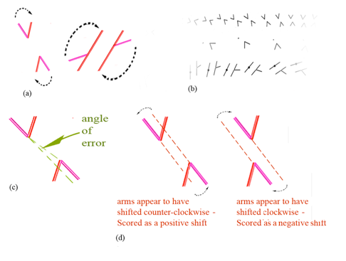
Scoring conventions in this study: (a) test arms would have always to rotate clockwise to align with inducing arms (ignoring the acute angle in figures showing obtuse and acute angles); (b) figures always rotate clockwise; (c) alignment errors are measured in degrees of angular deviation from objective alignment; (d) illusory counter-clockwise shifts in arm position are scored as positive, and clockwise shifts as negative.
My test arms would have always to rotate clockwise to align with inducing arms, in figures presenting only acute or obtuse angles, as shown in figure (a). In figures presenting both obtuse and acute angles, it’s the obtuse angle whose test arm would have to rotate clockwise to meet the inducing the inducing arm. Rotation of the figures is always clockwise, as in the segment of rotating figures at figure (b). Zero is always with test arms pointing at twelve o’clock (vertical), and the angle of rotation of the test arm is shown along the horizontal axis in every graph. Misalignment error is measured as an angle, as at figure (c) in degrees, and comprises the vertical axis in every graph. Finally, positive and negative measurements of misalignment follow the convention shown in figure (d). Whenever an apparent misalignment suggests a clockwise shift in test arm position, the shift is scored as negative. Whenever test arms present an anti-clockwise shift, the result is scored as positive. But remember that the rule would only apply with figures in the handedness we have settled on, with test arms (considering only the obtuse angles in full figures) clockwise from inducing arms.
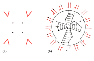
I've translated data from the other studies cited, as well as my own results from trials with mirror symmetric figures, into that scheme. That seems acceptable, since similar misalignment effects tend to be reported in mirror symmetrical figures, and with rotation through quadrants, as shown to the right.

In the study on this site, results are usually pooled for mirror and rotational symmetrical versions of the same figure, like the mirror symmetrical angle and dot figure to the left above. General trends are revealed more clearly by pooling results, but at the cost of some detailed variation. For example, there’s a clear “propeller” pattern to the results to the right above (redrawn from Weintraub and Krantz (1971, figure 5), but with variation from quadrant to quadrant.
However, pooling results from such variants does involve some loss of information. For example, the figure to the right shows misalignment with rotation of a one-armed Poggendorff figure, redrawn from Weintraub and Krantz (1971, their fig.5). Scores are shown in polar co-ordinates, and the “propeller blades” of the figure show results from each quadrant that are similar, but by no means identical. The researchers in that study noted that the variation, especially in the lower quadrant, almost certainly does have a physiological basis. But if the assumption is made that such variations are probably minor anomalies, they can be seen as masking much more overall, symmetrical effects, which emerge only when we pool the data within quadrants. For a radical example see Greene (1994).